
Solar Panels & Battery Banks: The Complete Build Guide
Everything needed to specify, size, wire and commission a photovoltaic system with storage — from the physics of a silicon cell to the exact cable cross-section, fuse rating and string configuration for your build. Covers every mainstream panel technology and battery chemistry, an interactive sizing calculator, and the wiring rules and grid-connection limits that change from one country to the next.
Read this before you touch a panel. A photovoltaic module produces voltage whenever light falls on it — there is no off switch, and a string of modules can sit at several hundred volts DC in daylight. DC arcs do not self-extinguish the way AC arcs do. A lithium or lead-acid battery bank can deliver thousands of amps into a short circuit, vaporizing a dropped spanner and causing severe burns. Never work on a live array, always cover modules or disconnect at the combiner before handling DC conductors, never connect or disconnect MC4 connectors under load, and fit overcurrent protection at the battery before anything else. In most countries the final connection to your home's distribution board or the utility grid must legally be made and signed off by a licensed electrician — see the Regional Rules tab. This guide is educational reference material, not a substitute for your equipment's manuals or your local electrical code.

Sunlight arrives as photons. When a photon with enough energy strikes a silicon cell it knocks an electron loose; the cell's internal electric field — created by a junction between differently doped silicon layers — pushes that electron in one direction. Multiply by billions of photons per second across dozens of cells wired in series and you get a usable direct current at roughly 30–50 volts per module. Everything downstream exists to make that raw, weather-dependent DC useful at the moment you actually need it.
Energy path of a hybrid system. In a pure off-grid build the dashed utility leg simply does not exist; in a grid-tied system without storage, the battery branch does not exist.
| System | Battery? | Works in a blackout? | Best for |
|---|---|---|---|
| Grid-tied | No | No — anti-islanding shuts it down | Lowest cost per kWh where net metering or a feed-in tariff exists |
| Hybrid (grid + storage) | Yes | Yes, on backed-up circuits | Most homes today: self-consumption plus outage protection |
| Off-grid | Yes, mandatory | N/A — there is no grid | Cabins, remote land, farms, anywhere a utility connection costs more than the system |
| Mobile (RV / van / boat) | Yes | N/A | 12 V or 24 V DC-centric builds with modest AC loads |
| Plug-in balcony | Usually no | No | Renters and apartments in countries that permit it (see Regional Rules) |
Work through it in order, or jump straight to the calculator if you already know your loads. Every tab is written to stand alone, and the calculator's outputs feed directly into the shopping list on the last tab.
Planning a build? Post it before you buy.
Share your load list and location in the Solar & Off-Grid board and have other builders sanity-check your string voltage, battery bank and cable runs. It is far cheaper than returning a controller that cannot handle your array.
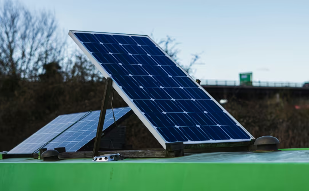
Every silicon module on the market is a variation on the same idea — a wafer with a p-n junction — but the way the rear surface is passivated and the contacts are made determines efficiency, how the panel behaves when hot, how fast it degrades, and what it costs. Since around 2023 the industry has pivoted hard from PERC to TOPCon, with heterojunction and back-contact occupying the premium end.
| Technology | Typical module efficiency | Temp. coefficient (Pmax) | Annual degradation | Typical power warranty | Where it wins |
|---|---|---|---|---|---|
| Mono PERC (p-type) | 20.0–21.5% | ~−0.35%/°C | ~0.5%/yr | 25 yr → ~80–84% | Lowest cost per watt; plentiful supply |
| TOPCon (n-type) | 22.0–23.5% | ~−0.30 to −0.32%/°C | ~0.4%/yr | 30 yr → ~87–88% | Best all-round value today |
| HJT | 21.5–23.0% | ~−0.24 to −0.26%/°C | ~0.25–0.30%/yr | 25–30 yr → ~90–92% | Hot climates; longest useful life |
| IBC / back-contact | >24% | ~−0.26 to −0.29%/°C | ~0.25–0.35%/yr | 25–30 yr → ~88–92% | Small or awkward roofs; maximum kWh per m² |
| Polycrystalline | 15–17% | ~−0.39 to −0.45%/°C | ~0.7%/yr | 20–25 yr → ~80% | Nothing, in new builds |
| CdTe thin-film | 17–19% | ~−0.28 to −0.34%/°C | ~0.3–0.5%/yr | 25 yr → ~80–88% | Utility scale, hot and humid climates |
| CIGS / a-Si flexible | 10–16% | ~−0.30 to −0.36%/°C | ~0.5–1.0%/yr | 10–20 yr, varies widely | Curved and weight-limited surfaces |
How to read the temperature coefficient. It tells you how much power the module loses for every degree above 25 °C. A panel on a dark roof in summer commonly reaches 60 °C. At −0.35%/°C that is 35 × 0.35 = 12.3% of nameplate power gone; at −0.26%/°C it is only 9.1%. In a hot climate that difference is worth more than a point of rated efficiency.
Two panels using identical cells can behave very differently depending on how the module is built. These are the construction terms that actually change your design.
Half-Cut & Third-Cut Cells
Cells are laser-cut in half, halving the current through each and therefore quartering resistive losses (I²R). The module is wired as two independent halves, so shading the bottom row no longer kills the whole panel. Effectively standard on modern modules — if a datasheet does not mention it, ask why.
Bifacial
A transparent or glass rear sheet lets the cells harvest light reflected off the ground behind them. Real-world gain is 5–15% over a light surface (gravel, white membrane, snow) and close to zero flush-mounted on a dark roof. Worth paying for on ground mounts, carports and flat roofs with a reflective membrane; rarely worth it otherwise. Note that bifacial gain also raises string current, which must be included in fuse and conductor sizing.
Glass-Glass vs Glass-Backsheet
Glass on both faces resists moisture ingress, PID and micro-cracking far better than a polymer backsheet, and is why glass-glass modules carry 30-year warranties. The cost is weight — check your roof structure and mounting rail spans before specifying them.
Busbars: 5BB → MBB → 0BB
More, thinner busbars shorten the path electrons travel through the emitter and reduce shading. Multi-busbar (9–16 round wires) is now normal; zero-busbar designs replace printed busbars with fine wires pressed onto the cell, cutting silver use and boosting output slightly.
Bypass Diodes
Typically three per module, in the junction box. When a cell group is shaded, its diode conducts around it so the rest of the string keeps producing and the shaded cell does not become a hot spot. This is why partial shade costs you a third of a panel, not the whole string — but it is also why a failed diode shows up as a mysteriously underperforming string.
Cell Format: M6, M10, G12
Wafer size drives module current. Larger G12 (210 mm) wafers make high-power modules but push string current up toward 18–20 A, which changes your fuse, connector and conductor choices. A 450 W module and a 700 W module are not interchangeable just because both are "one panel."
Certification Marks
Look for IEC 61215 (design qualification) and IEC 61730 (safety), plus UL 61730 for North America and a fire class rating. In salt-spray or ammonia environments (coastal, agricultural) also look for IEC 61701 and IEC 62716.
- Plenty of roof space, tight budget? Buy PERC or mid-tier TOPCon on lowest cost per watt. Efficiency only matters when area is scarce.
- Small or complicated roof? Pay for TOPCon, HJT or IBC — you are buying watts per square meter, not watts per euro.
- Hot climate (roof regularly above 45 °C)? Prioritize the temperature coefficient over the headline efficiency figure.
- Ground mount or carport over gravel? Bifacial glass-glass, raised and tilted, pays for itself.
- Van, boat or shed roof? Rigid framed panels whenever the structure allows; flexible laminates only where it genuinely does not.
- Any mix-and-match? Never put different models in the same series string. Mismatched current drags the whole string down to the weakest module.
Beware "high wattage" bargains. Efficiency figures on marketplace listings are frequently cell efficiency (or outright fiction) rather than module efficiency. Sanity-check the number yourself: divide rated watts by the module's area in m² and divide by 1000 W/m². A 2.0 m² module rated 450 W is 22.5% efficient. If the arithmetic does not support the claim, the datasheet is not trustworthy — and neither is anything else on it.
Six numbers on a module datasheet decide whether your system works or destroys a controller. Everything else is marketing. Learn these and you can specify any array from any manufacturer.
| Symbol | Name | What it means | What you use it for |
|---|---|---|---|
| Pmax | Maximum power | Rated output at STC, in watts. The number on the box. | Array sizing, energy yield estimates |
| Voc | Open-circuit voltage | Voltage with nothing connected — the highest voltage the module ever produces. Rises as temperature falls. | Maximum string length. The single most safety-critical figure. |
| Isc | Short-circuit current | Current into a dead short — the highest current the module ever produces. | Fuse, breaker and conductor sizing |
| Vmp | Voltage at max power | Operating voltage at peak output, typically 78–84% of Voc. | Matching the array to the MPPT operating window |
| Imp | Current at max power | Operating current at peak output, typically 92–96% of Isc. | Expected working current, MPPT input limit |
| βVoc | Temp. coefficient of Voc | How much Voc changes per °C, usually around −0.25 to −0.30%/°C. | Cold-weather Voc correction — see the worked example below |
STC (Standard Test Conditions) is a laboratory fiction: 1000 W/m² irradiance, cell temperature exactly 25 °C, air mass 1.5. It exists so modules can be compared fairly, not to predict field output.
NOCT / NMOT (Nominal Operating Cell Temperature / Nominal Module Operating Temperature) is measured at 800 W/m², 20 °C ambient, 1 m/s wind — much closer to a real roof. A module's NMOT power is typically 73–78% of its STC power. This is not a defect; it is physics, and it is already accounted for in the derate factor the calculator on this page uses.
Silicon voltage rises as it gets colder. A string sized on STC Voc can exceed its controller's maximum input voltage on the first frosty, bright morning — and an over-voltage event usually destroys the MPPT instantly, with no warranty cover. Always size strings on corrected Voc at your record low temperature, not at 25 °C.
Use your true record low, not the average winter temperature. Many codes require the lowest expected ambient temperature for the site; some jurisdictions specify an extreme annual mean minimum from a published dataset. When in doubt, be pessimistic — the cost of one fewer module per string is trivial next to a dead controller.
A 450 W TOPCon module: Pmax 450 W, Voc 49.5 V, Isc 11.6 A, Vmp 41.8 V, Imp 10.8 A, βVoc −0.27%/°C. Controller: 250 V max PV input, 100 A charge current, 48 V battery bank. Site record low −10 °C, record high ambient 38 °C.
- Power tolerance quoted as ±5% rather than 0/+5%. Negative tolerance means you may legitimately receive less than you paid for.
- No IEC 61215 / 61730 (or UL 61730) certification number, or certification for a different model number.
- Efficiency that does not match watts ÷ area. Do the division every time.
- Missing temperature coefficients. Without βVoc you cannot legally or safely size a string.
- Mechanical load rating absent or below your local wind/snow requirement (commonly 2400 Pa front / 5400 Pa snow).
- "Up to" wattage in the product title that differs from Pmax in the electrical table.
- A 25-year warranty from a company with no local entity — a warranty you cannot enforce has no value.
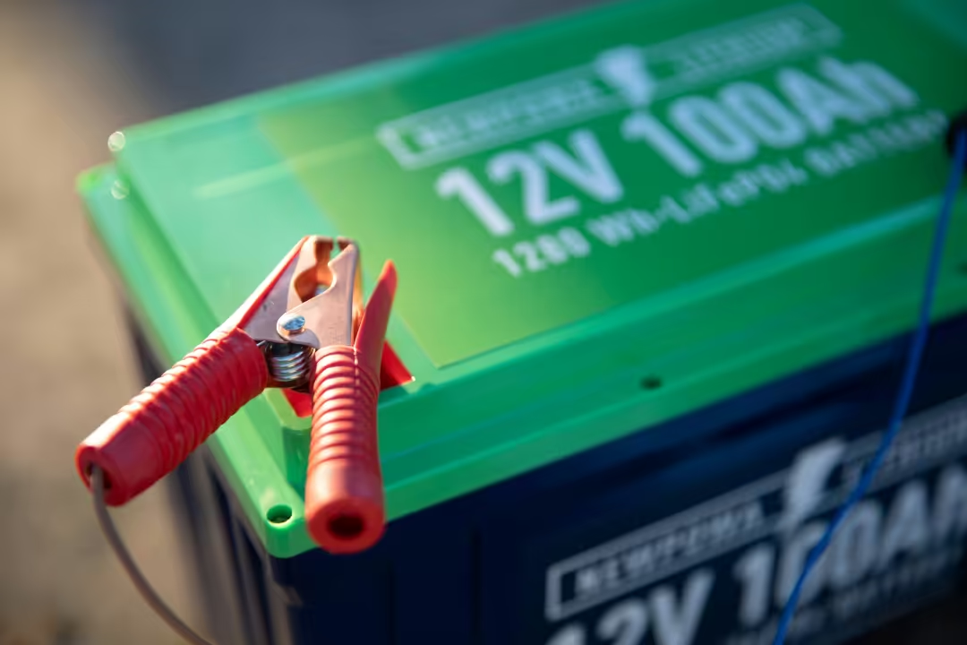
The battery is usually the most expensive component and the first one to fail, so choosing the chemistry is the highest-leverage decision in the whole build. Compare on usable kWh over the life of the pack, never on nameplate kWh or sticker price: a lead-acid bank you may only discharge to 50% and that lasts 500 cycles is dramatically more expensive per delivered kWh than a LiFePO₄ pack you can take to 90% for 6000 cycles.
| Chemistry | Usable DoD | Cycle life (to 80% SoH) | Energy density | Round-trip eff. | Charge temp limit | Notes |
|---|---|---|---|---|---|---|
| LiFePO₄ (LFP) | 80–90% | 3000–6000+ | 90–160 Wh/kg | 95–98% | 0 °C min | The default choice for home and mobile storage. Very stable chemistry, no thermal-runaway propagation in normal abuse, long life, tolerant of partial-state-of-charge use. |
| NMC / NCA | 80–90% | 1500–4000 | 150–260 Wh/kg | 92–96% | 0 °C min | Highest energy density — why EVs use it. For stationary storage the density advantage rarely matters, and the thermal risk profile is higher than LFP. |
| Sodium-ion (Na-ion) | 85–90% | 2000–5000 | 75–160 Wh/kg | 90–95% | −20 °C min | The interesting newcomer: no lithium, no cobalt, genuinely good cold-weather charging, can be safely stored at 0 V. Fewer products, less field history. |
| LTO (lithium titanate) | 90–95% | 10,000–20,000 | 50–80 Wh/kg | 95–98% | −30 °C min | Effectively lifetime-proof and extremely fast-charging, but bulky, low voltage per cell and very expensive. Niche. |
| AGM lead-acid | 50% | 400–800 | 30–40 Wh/kg | 80–85% | −20 °C min | Sealed, maintenance-free, cheap up front. Hates being left partially charged. Still reasonable for small backup or a starter battery. |
| Gel lead-acid | 50–60% | 500–1000 | 30–40 Wh/kg | 80–85% | −20 °C min | Better deep-cycle tolerance than AGM, but intolerant of high charge currents and easily damaged by an over-voltage absorb setting. |
| Flooded lead-acid (FLA) | 50% | 1000–2000 | 25–40 Wh/kg | 75–85% | −20 °C min | Cheapest per nameplate kWh and repairable, but needs watering, equalization charges, a vented enclosure and an upright installation. Outgasses hydrogen. |
| Nickel-iron (NiFe) | 80% | 10,000+ | ~25 Wh/kg | 65–80% | −20 °C min | Nearly indestructible and decades-long life, but poor efficiency, heavy self-discharge, constant watering and high cost. A curiosity, not a recommendation. |
The rule that catches people out: standard lithium cells must not be charged below 0 °C — doing so plates metallic lithium on the anode, permanently destroying capacity and creating an internal short risk. Discharging below freezing is fine. If your bank lives in an unheated garage, shed or van in winter, buy a pack with integrated low-temperature charge cut-off and self-heating, or choose sodium-ion. This is not a warranty technicality; it is how cold-climate lithium banks actually die.
Two 10 kWh banks are not equal. The lead-acid bank gives you 5 kWh before you start shortening its life; the LFP bank gives you 9 kWh and survives roughly six times as many cycles doing it. To store 9 usable kWh in lead-acid you must buy an 18 kWh nameplate bank — and find somewhere to put roughly 500 kg of it.
C-rate expresses current relative to capacity. 1C on a 100 Ah battery is 100 A; 0.5C is 50 A. It governs how much power (not energy) the bank can deliver, and it is what determines whether your bank can start an air conditioner or run an induction hob.
Lead-acid also loses capacity as you pull harder (Peukert's effect): a 100 Ah bank discharged in 5 hours may deliver only 75 Ah. Lithium is essentially immune to this, which is another reason its usable capacity advantage is bigger than the DoD numbers alone suggest.
Series adds voltage
Four 12 V 100 Ah batteries in series = 48 V 100 Ah (still 4.8 kWh). Higher voltage means lower current for the same power, which means thinner cable, smaller fuses and lower losses. For any system above about 1500 W, go to 24 V; above 3000 W, go to 48 V.
Parallel adds capacity
Four 12 V 100 Ah in parallel = 12 V 400 Ah (also 4.8 kWh) but at four times the current for a given load. Parallel strings must be identical in chemistry, capacity, age and state of charge, and must be cabled so every battery sees the same resistance — diagonal (cross-corner) takeoff, or a proper busbar with equal-length leads. Unequal cabling silently overworks one battery until it fails first.
Never mix
- Different chemistries on the same bus (lithium and lead-acid need different charge profiles).
- Different capacities or brands in the same string.
- New batteries into an old bank — the old ones drag the new ones down to their level.
- Batteries at different states of charge, without balancing them first at the same voltage.
The BMS is not optional
Every lithium bank needs a Battery Management System that balances cells, cuts off on over/under-voltage, over-current and out-of-range temperature. Check its continuous and peak current rating matches your inverter: a 200 A BMS on a 48 V bank caps you at about 9.6 kW no matter what the cells could do. Prefer a BMS that communicates with your inverter over CAN or RS485 — closed-loop control beats voltage-guessing.
- Lithium: avoid sitting at 100% for long periods. If your system routinely fills by noon, set the charge target to about 90% SoC and let it float lower — the capacity you give up is repaid many times in calendar life.
- Lead-acid: the opposite. Return it to a full charge as soon as possible after every discharge; time spent partially charged is what sulfates the plates.
- Temperature is the silent killer. Lithium life roughly halves for every 10 °C above about 30 °C. Install the bank somewhere cool, dry and shaded — never in direct sun or against a hot wall.
- Set the charge profile correctly. Absorb and float voltages differ by chemistry and must be temperature-compensated for lead-acid (typically −3 to −5 mV per cell per °C). Lithium needs no temperature compensation, and applying a lead-acid profile to lithium will over-charge it.
- Size for depth, not just capacity. A bank cycled to 30% DoD daily will outlive an identical bank cycled to 80% by several times over.
- Storing it? Lithium stores best around 50–60% SoC in a cool place; lead-acid must be stored fully charged and topped up periodically.
- Flooded lead-acid vents hydrogen while charging. It requires a ventilated enclosure and no ignition sources — never in a sealed cupboard, never in a living space.
- Lithium banks should sit on a non-combustible surface with clearance around them, and many local codes now limit indoor kWh and require specific separations from exits and habitable rooms.
- Remove watches, rings and metal bracelets before working on a bank. Use insulated tools and work one terminal at a time.
- Torque terminals to the manufacturer's specification with a torque wrench. Loose terminals are the leading cause of battery-bank fires; over-tightened ones crack the posts.
- Label polarity clearly and fit terminal covers. Fit the main fuse last, on the positive side, with the bank isolated.
- Check whether your insurer and local building code require notification for a fixed battery installation — in many countries they now do.
Not sure which chemistry fits your climate?
Cold garage, hot roof space, marine humidity or a weekend-only cabin all push the answer in different directions. Describe your install location on the forum and get specific advice.
A charge controller sits between the array and the battery and decides how energy is delivered. There are only two kinds, and the difference is not subtle: a PWM controller is a fancy switch, while an MPPT controller is a DC-to-DC converter with a tracking algorithm.
| PWM | MPPT | |
|---|---|---|
| How it works | Connects the array directly to the battery, pulsing the connection. The array is dragged down to battery voltage. | Runs the array at its maximum power point and converts the surplus voltage into extra charging current. |
| Typical harvest | Baseline | 15–30% more energy, and much more in cold or low light |
| Array voltage | Must roughly match battery voltage (a "12 V panel" on a 12 V bank) | Array voltage can be far higher than the battery — enables long, thin, cheap cable runs |
| Panel choice | Only nominal 12/24 V panels, which are a shrinking and overpriced niche | Any standard grid-tie module, which is where the cheap watts are |
| Cost | Low | 2–4× higher |
| Sensible use | Under about 200 W: trickle charging, gate openers, small sheds | Everything else, without exception |

Two independent limits must both be satisfied, and the controller's rating is in output amps to the battery, not array watts.
This is the argument for 48 V. Doubling bus voltage halves the current everywhere downstream, which halves the required copper and lets you use a smaller, cheaper controller for the same array.
- Correct chemistry profiles, including a user-definable profile. A controller with only "AGM/Gel/Flooded" presets is wrong for lithium.
- Temperature sensor input for lead-acid compensation, and a battery-voltage sense lead so the controller regulates at the terminals rather than at its own output.
- Bluetooth or Ethernet monitoring. Not a toy — production and state-of-charge history is how you catch a failing panel, a dirty array or a dying cell before it costs you.
- Multiple independent MPPT trackers if your roof faces more than one direction. Arrays at different orientations must never share a tracker.
- Documented over-paneling allowance, so a deliberately oversized array clips gracefully instead of faulting.
- Real ingress protection (IP65+) if it will be mounted anywhere other than a dry indoor space.
DC coupled: panels charge the battery through an MPPT, then a single conversion to AC. Fewer conversions means higher round-trip efficiency (typically 2–5% better) and it is the natural approach for a new build.
AC coupled: an existing grid-tie inverter stays in place and a separate battery inverter is added alongside. Energy goes DC→AC→DC→AC to reach the battery and come back out, so efficiency suffers — but it is far and away the easiest way to retrofit storage onto an existing solar installation without replacing what works.
- Continuous rating must exceed the sum of everything that may realistically run at once — not the sum of everything you own.
- Surge rating must cover the largest motor start. Compressors, well pumps, table saws and air conditioners draw 3–7× running current for a fraction of a second. Check both the surge watts and how long the inverter can hold them.
- Idle draw matters in off-grid. A large inverter idling at 40 W burns about 1 kWh a day doing nothing — often more than your actual overnight loads. Look for a low no-load figure and a search/standby mode.
- Pure sine wave, always. Modified sine overheats motors, buzzes audibly through audio gear, and damages some medical and electronic equipment.
- Match the phase configuration your country uses: 120/240 V split-phase in North America, 230 V single-phase or 400 V three-phase in Europe (see Regional Rules).
- Grid-interactive? The unit must hold the certification your grid operator requires — UL 1741 SA/SB and IEEE 1547 in North America, EN 50549 / the relevant national annex in Europe, AS/NZS 4777.2 in Australia and New Zealand. A non-certified inverter will not be approved for connection, however good it is.
A cable must satisfy two separate requirements, and the larger of the two wins. Sizing for one and ignoring the other is the most common wiring error in DIY solar — and on the low-voltage DC side, voltage drop almost always dictates a larger cable than ampacity alone would suggest.
Test 1 — Ampacity (safety)
The conductor must carry the maximum continuous current without exceeding its insulation temperature rating, after applying derating factors for ambient temperature, grouping and conduit fill. This is what stops the cable from becoming a heater.
Test 2 — Voltage drop (performance)
Every meter of cable wastes some voltage as heat. On a 12 V system a 3% drop is only 0.36 V — and that tiny loss can be enough to stop a charge controller from ever reaching absorb voltage. Target ≤3% on battery and charging circuits and ≤1–2% on the battery-to-inverter run.
| AWG | mm² (actual) | Nearest metric size | Indicative DC ampacity* |
|---|---|---|---|
| 14 | 2.08 | 2.5 | ~20 A |
| 12 | 3.31 | 4 | ~25 A |
| 10 | 5.26 | 6 | ~35 A |
| 8 | 8.37 | 10 | ~50 A |
| 6 | 13.3 | 16 | ~65 A |
| 4 | 21.2 | 25 | ~85 A |
| 2 | 33.6 | 35 | ~115 A |
| 1/0 | 53.5 | 50–70 | ~150 A |
| 2/0 | 67.4 | 70 | ~175 A |
| 4/0 | 107.2 | 95–120 | ~250 A |
*Indicative only. Real ampacity depends on insulation rating (90 °C PV wire behaves very differently from 60 °C building wire), ambient temperature, whether the cable is in free air, conduit or bundled, and your national code's tables. Always confirm against the table that applies where you live — NEC 310 in North America, IEC 60364-5-52 / BS 7671 Appendix 4 in Europe and the UK, AS/NZS 3008 in Australia.
| Location | Device | Sizing rule |
|---|---|---|
| Each PV string (3+ strings in parallel) | PV-rated gPV fuse in a combiner | NEC: 1.56 × Isc. IEC: per module datasheet max series fuse rating |
| Combiner output → controller | DC breaker or fuse + isolator | 1.25 × total array Isc (NEC uses 1.56×) |
| Controller → battery | DC breaker or fuse | 1.25 × controller rated output current |
| Battery → inverter | Class T or equivalent high-AIC fuse | 1.25 × max continuous inverter DC current, below cable ampacity |
| Each parallel battery string | Fuse per string | Per manufacturer; protects against inter-string fault current |
| Inverter AC output | AC breaker / RCD as required locally | Per national wiring rules |
DC-rated means DC-rated. An AC breaker used on a DC circuit may not be able to extinguish the arc when it opens, because DC current never crosses zero. Every protective device on the DC side must be explicitly rated for DC at or above your system voltage, with an adequate interrupting capacity (AIC) for your battery's available fault current.
Equipment bonding
Every module frame, rail and metal enclosure must be bonded together with a continuous conductor and connected to the building's earthing system. Use listed bonding clips or washers that bite through anodizing — a bolt through a painted rail is not a bond. This is what makes a fault current trip a protective device instead of energizing your handrail.
System grounding
Modern transformerless inverters are usually designed for a floating (ungrounded) array with insulation monitoring, so do not bond a PV conductor to earth unless the equipment specifically requires it. On the battery side, whether and where the negative is bonded depends on the inverter and your national rules — follow the manual exactly, and never create two bonding points.
Surge protection (SPD)
A roof array is an elevated conductive structure with long cable runs — an excellent antenna for induced surges from nearby lightning. Fit Type 2 SPDs on the DC side at the inverter and, if the run exceeds roughly 10 m, at the array end too, plus an AC-side SPD at the distribution board. In high-lightning regions consider Type 1 and a proper lightning protection system. Keep DC positive and negative conductors close together along their whole route to minimize the induction loop area — this costs nothing and is remarkably effective.
Arc-fault and rapid shutdown
In the US, NEC requires DC arc-fault protection and module-level rapid shutdown on buildings, so that firefighters can de-energize conductors at the array. Europe generally does not mandate module-level shutdown but many countries require an accessible DC isolator, and firefighter switches are required or recommended in several. See Regional Rules.
- Never mate connectors from different brands, even when both are called "MC4-compatible". Mismatched contact geometry causes high-resistance joints that overheat — a well-documented cause of rooftop fires. Use one brand throughout, crimped with that brand's tool.
- Use double-insulated, UV-stable PV cable (H1Z2Z2-K in Europe, PV Wire or USE-2 in North America) for all exposed DC runs. Ordinary building or automotive cable perishes within a couple of seasons in sunlight.
- Support cable properly. No cable should rest on a roof surface, hang in a loop that collects water, or be secured with plastic ties that will fail in UV. Use UV-rated clips into the rails.
- Crimp, do not solder, high-current battery lugs — a soldered joint goes brittle and can wick solder up the strands, creating a stress riser. Use a proper hydraulic crimper and heat-shrink the joint.
- Torque everything to spec and mark each fastener with a paint pen so a loose connection is visible at a glance on future inspections.
- Label everything: polarity, circuit function, isolation points, and a placard at the main board stating that the building has a second power source.
- Measure string Voc with a meter and compare against the calculated value — a low reading means a reversed module or a failed diode.
- Verify polarity at every connection before closing any isolator. Reversed DC polarity destroys controllers.
- Test insulation resistance between array conductors and earth.
- Confirm continuity of the equipment bonding conductor from the furthest module frame to the earth bar.
- Check every string's Isc matches within a few percent; an outlier indicates shading, soiling or a fault.
- Confirm the controller's battery profile matches the actual chemistry before connecting the bank.
- Operate every isolator and verify the system genuinely de-energizes where the labels say it will.
- Thermal-scan connections under load after a few weeks — a hot terminal is a warning you can still act on.
In much of Europe, commissioning documentation follows IEC/EN 62446-1, which sets out exactly which tests and records are required for a grid-connected PV system. It is a genuinely useful checklist even for an off-grid build.
Getting a module's angle roughly right is worth a few percent. Getting shading wrong can cost you a third of the system's output. Prioritize accordingly.
Azimuth (which way it faces)
- Northern hemisphere: true south is optimal. East or west facing typically costs 10–20% annually.
- Southern hemisphere: true north is optimal — the mirror image.
- Use true (geographic) north/south, not magnetic. Magnetic declination can be 10° or more depending on where you are.
- A west-facing array produces less total energy but more of it in the late-afternoon peak — which can be worth more than raw kWh under a time-of-use tariff.
- Splitting an array east/west on a flat roof flattens the production curve and often suits self-consumption better than a single south-facing block.
Tilt angle
- Year-round rule of thumb: tilt ≈ your latitude.
- Winter-optimized (critical for off-grid, where December decides your bank size): latitude + 15°.
- Summer-optimized (irrigation, seasonal cabins, air conditioning): latitude − 15°.
- Never go below about 10° on a fixed array: rain needs to run off and carry dust with it. Flat-mounted panels soil fast and can lose 5–10% to dirt.
- Adjustable tilt sounds appealing and is almost never worth the hardware and the labor — extra panels usually cost less than seasonal adjustment mechanisms.
- Tracking systems add 15–35% yield but also moving parts, maintenance and significant cost. Sensible on some ground mounts, rarely on a roof.
- Check the structure first. A framed array adds roughly 12–18 kg/m² dead load plus wind uplift, which is often the governing case. Older roofs, and anything with a history of sagging, need an engineer's opinion — not an assumption.
- Fix into rafters, never into battens or sheathing alone. Uplift forces on a panel in a storm are considerable and act to peel it off.
- Flashing is the whole job on a pitched roof. Every penetration needs a proper flashed mount integrated under the course above; sealant alone is a leak with a delay timer.
- Leave an air gap of at least 100 mm behind the modules. Cooler panels produce more, and the gap prevents heat build-up under the roof covering.
- Flat roofs usually take ballasted tilt frames to avoid penetrations — but ballast is weight, so the structural check matters even more. Respect row spacing so rows do not shade each other in winter.
- Respect fire-service setbacks from ridges and edges where your jurisdiction requires them, and keep an access path.
- Fit bird mesh around the array perimeter. Pigeons nesting underneath cause shading, corrosion and a genuinely unpleasant cleanup.
- Ground mounts are the easiest to build, service and clean, run cooler than roof arrays and let you pick the perfect angle. They need foundations sized for wind uplift and frost depth, plus a plan for keeping vegetation down.
- Bifacial modules shine here — raise the array and put light gravel or a reflective surface beneath it.
- Pole mounts suit small arrays and snowy sites, keeping panels above drift height, and make seasonal tilt adjustment genuinely practical.
- Planning permission is more often required for ground mounts than for roof arrays in many countries — check before you pour concrete.
- RV and van roofs: bond rigid panels to the roof with structural adhesive on properly prepared surfaces, or use riveted L-brackets with sealant. Leave an air gap wherever you can, and route cables through a sealed, UV-stable roof gland.
- Marine: everything must be 316 stainless or anodized aluminium, tinned copper conductors throughout, and fittings must survive continuous vibration and salt spray. Look for IEC 61701 salt-mist certification on the modules.
- Rinse modules when visibly soiled — cool water, soft brush, early morning or evening. Never cold water on hot glass, and never a pressure washer.
- Trim vegetation annually, before it starts casting a winter shadow.
- Inspect mounts, clamps and flashing after severe weather.
- Re-check terminal torque on the battery bank annually.
- Compare monthly production against the same month last year — a slow decline usually means soiling or a failing string, and it is invisible without records.
- In snowy climates, let snow slide rather than scraping it. A 30°+ tilt sheds most of it on its own.
Build your load list, tell it where you are and what you want to build, and it sizes the whole chain: battery bank, PV array, charge controller, inverter, cable cross-sections and overcurrent devices — in both AWG and mm², using the overcurrent convention of the region you select. Nothing is sent anywhere; every calculation runs in your browser.
Solar & Battery Bank Sizing Calculator
Off-grid, hybrid, RV, marine and backup systems — metric and imperial, US and international overcurrent rules.
1 · Location & Standards
Peak sun hours are planning estimates. For a site-specific figure use NREL PVWatts (worldwide), PVGIS (Europe, Africa, Asia) or the Global Solar Atlas, and enter it above.
2 · Daily Load Profile
| Appliance | Watts | Qty | Hrs/day | Type | Wh/day |
|---|
Set Type to AC for anything plugged into a mains socket and DC for 12/24/48 V loads wired straight to the battery (LED lighting, fridges, water pumps, fans in a van). DC loads skip the inverter, so they cost noticeably less energy.
3 · Storage
4 · Array & Electronics
5 · Cable Runs (one-way)
Recommended System
Energy Budget
Battery Bank
PV Array & String Configuration
Charge Controller & Inverter
Cables & Overcurrent Protection
Outputs are engineering estimates for planning and shopping, based on the figures you entered. They are not a substitute for a design signed off against your national wiring rules, and cable sizes must still be verified against the ampacity tables that apply where you live.
- Measure, do not guess, your loads. A plug-in energy meter on your fridge for 24 hours beats any wattage sticker — a compressor fridge rated 120 W may only run 30% of the time.
- Off-grid? Always size on the worst month, not the annual average. A bank sized on a June average will leave you dark in December.
- Add 20–25% headroom to the load list for the things you have not thought of. Every system grows.
- The default 25% system loss covers soiling, temperature, mismatch, wiring and controller efficiency. Raise it to 30–35% for hot climates, dusty sites or arrays with any shading.
- Autonomy days is a climate judgment: 1–2 days where sunshine is reliable and a generator exists, 3–5 days for a remote installation in a cloudy winter climate.
- A generator changes the maths entirely. With one, size the bank for 1–2 days and accept occasional charging; without, you are paying for the worst week of the year in copper and lithium.
Post your calculator output for a second opinion
Use Copy spec sheet above and paste the result into the forum. Experienced builders will spot the string voltage that is too close to the limit or the cable run you underestimated — before the parts arrive.
A design that is exemplary in Arizona can be non-compliant in Bavaria and unsellable in Queensland. The physics never changes; the mains voltage, the conductor sizing convention, the overcurrent multiplier, the maximum permitted DC voltage, who is allowed to make the final connection, and what you are paid for exported energy all do. Read this tab before you buy hardware — particularly if you are ordering from an overseas marketplace.
| North America | UK & Ireland | Continental Europe | Australia / NZ | |
|---|---|---|---|---|
| Mains supply | 120/240 V split-phase, 60 Hz | 230 V single-phase, 50 Hz | 230 V single / 400 V three-phase, 50 Hz | 230 V single / 400 V three-phase, 50 Hz |
| Conductor sizing | AWG, NEC 310 tables | mm², BS 7671 App. 4 | mm², IEC 60364-5-52 | mm², AS/NZS 3008 |
| PV overcurrent factor | 1.56 × Isc (1.25 × 1.25) | Per module max series fuse rating | Per module max series fuse rating | Per AS/NZS 5033 and module rating |
| Max array DC voltage | 600 V on dwellings, 1000 V elsewhere (check the current NEC edition adopted locally) | 1000 V typical domestic limit | 1000 V typical domestic limit; 1500 V utility scale | 600 V d.c. limit for many domestic arrays under AS/NZS 5033 |
| Rapid shutdown | Required on buildings (NEC 690.12), module-level | Not mandated; accessible DC isolation required | Not generally mandated; firefighter switch required or recommended in several countries | Rooftop isolator requirements per AS/NZS 5033 |
| DC arc-fault detection | Required (NEC 690.11) | Not mandated | Not generally mandated | Not generally mandated |
| Inverter certification | UL 1741 SA/SB, IEEE 1547-2018 | G98/G99, EN 50549 | EN 50549 + national annex (e.g. VDE-AR-N 4105, CEI 0-21) | AS/NZS 4777.2 |
| Commissioning docs | AHJ inspection + permit | BS 7671 certificate, MCS if claiming export payments | IEC/EN 62446-1 test report | CEC-accredited installer paperwork + DNSP approval |
The most expensive import mistake: buying a grid-tie or hybrid inverter certified for the wrong region. A unit holding UL 1741 will not be approved for a European grid connection, and one certified only to VDE-AR-N 4105 will not be accepted in Australia. Certification is regional, it is checked at connection, and no amount of correct wiring substitutes for it. Off-grid inverters with no grid connection are the one exception — but they still must match your mains voltage and frequency.
| Country | Key standards | Connection process | Plug-in / balcony PV | Export arrangement |
|---|---|---|---|---|
| United States | NFPA 70 (NEC) Art. 690, 705, 706; UL 1741; UL 9540 for storage | Permit from the AHJ, utility interconnection agreement, inspection. Licensed electrician required in most jurisdictions. | Historically not permitted; several states are now introducing tiered rules (e.g. a low-wattage no-permit tier plus a higher tier needing an electrician). Check your state and utility. | Net metering, net billing or avoided-cost, set state by state. Federal and state incentives change frequently — verify current status before budgeting. |
| Canada | CSA C22.1 (Canadian Electrical Code) Section 64; provincial amendments | Provincial permit and utility approval; CSA-certified equipment only. | Not generally permitted. | Net metering programs run provincially; terms differ substantially. |
| United Kingdom | BS 7671 Section 712; MCS 012/MIS 3002; Building Regs Part P | G98 notification for up to 16 A per phase (about 3.68 kW single-phase) — connect then notify the DNO. G99 application and approval before connecting anything larger. | No dedicated plug-in framework; a plug-in generator is not covered by G98 for a standard socket. | Smart Export Guarantee (SEG) — requires MCS (or equivalent) certification and tariffs vary hugely by supplier, so shop around. |
| Germany | VDE-AR-N 4105, VDE-AR-N 4100; VDE product standard for plug-in PV | Registration in the Marktstammdatenregister is mandatory for every system; grid operator notification via a registered installer for fixed systems. | Permitted — up to 800 W inverter output (raised from 600 W in 2024), with a simplified registration route and tenant/owner rights strengthened by the Solarpaket reforms. | EEG feed-in tariff, with the rate set at commissioning and fixed for 20 years. |
| France | NF C 15-100; UTE C 15-712-1 for PV | Enedis self-consumption agreement; a Consuel conformity attestation is required before the grid connection is energized. | Plug-in kits are widely sold; a declaration to Enedis is expected. | Obligation d'achat purchase tariffs plus a self-consumption premium, revised periodically. |
| Spain | REBT (ITC-BT-40); RD 244/2019; RD 1183/2020 | Registration with the autonomous community; simplified route for small self-consumption installations. | Small plug-in systems fall under the self-consumption framework; regional interpretation varies. | Compensación simplificada de excedentes — surplus credited on the bill. The old "sun tax" was abolished in 2018. |
| Portugal | DL 15/2022 (UPAC regime); RTIEBT wiring rules; DGEG oversight | Tiered by power: small systems without grid injection are exempt from prior control; above that and up to 30 kW a mera comunicação prévia is filed through the SERUP portal; larger systems need registration and an operating certificate. | Permitted within the exemption tier — the threshold was raised to 800 W AC in 2026, aligning with the EU norm. Confirm the figure currently in force with DGEG before relying on it. | Surplus sold to a trader at an agreed price, or under a collective self-consumption / energy-community arrangement. |
| Italy | CEI 0-21 (LV connection); CEI 82-25 | Connection request via the distributor (e-distribuzione or local DSO), then GSE registration. | Plug-in systems permitted subject to the national framework and DSO notification. | Managed through GSE. The historic Scambio sul Posto arrangement has been closed to new entrants — check which scheme currently applies. |
| Netherlands | NEN 1010; NEN 7250 for building-integrated | Register the system with the grid operator via the national register; installer certification expected. | Permitted, subject to inverter standards. | Salderingsregeling (net metering) is being phased out — the terms for new systems are changing, so verify the current position before sizing for export. |
| Australia | AS/NZS 5033 (array install); AS/NZS 4777.1/.2 (grid connection); AS/NZS 3000; AS/NZS 5139 (battery) | Pre-approval from the DNSP, installation by a CEC-accredited installer (mandatory to claim STCs), then a certificate of electrical safety. | Not permitted — all grid-connected generation must be installed by a licensed, accredited installer. | Small-scale Technology Certificates up-front, plus state and retailer feed-in tariffs. Export limits (often 5 kW per phase) are common. |
| New Zealand | AS/NZS 3000; AS/NZS 4777.2 | Application to the local lines company; licensed electrician required. | Not permitted. | Buy-back rates negotiated with your retailer; no national tariff. |
| South Africa | SANS 10142-1; NRS 097-2-1 for embedded generation | Registration with the municipality or Eskom, plus a certificate of compliance from a registered person. Requirements are enforced more consistently than they once were. | Not formally recognized. | Varies by municipality; many allow offset but not payment for net export. |
| Brazil | ABNT NBR 16690; ANEEL rules under Lei 14.300/2022 | Access request to the distributor, with the parecer de acesso issued before connection. | Not formally recognized. | Energy compensation system, with grandfathering rules for systems connected before the legal transition. |
| Japan | JIS standards; JET certification | Utility interconnection application; note the split grid frequency — 50 Hz in eastern Japan, 60 Hz in the west, at 100 V nominal. | Not formally recognized. | FIT / FIP schemes with rates revised annually. |
Rules move faster than guides do. Grid codes, plug-in wattage limits, export tariffs and tax incentives are revised on a scale of months, not decades. Treat this table as an orientation map, then confirm the current position with your distribution network operator, your national energy regulator, and a licensed local electrician before you commit money.
The same array produces radically different energy depending on where it stands. These are typical annual averages in peak sun hours per day — the number of hours of full 1000 W/m² sunshine equivalent.
| Region | Annual avg PSH | Typical worst month |
|---|---|---|
| US Southwest, Middle East, North Africa | 5.8–6.5 | 4.2–5.0 |
| Mediterranean, US South, Australia | 4.6–5.5 | 2.6–3.6 |
| Central Europe, US Midwest & Northeast | 3.2–4.4 | 1.2–2.2 |
| UK, Ireland, Benelux, Nordic south | 2.7–3.2 | 0.7–1.2 |
| Equatorial (low seasonality, high cloud) | 4.2–5.0 | 3.6–4.4 |
Why off-grid design lives or dies on the worst month. In northern Europe the December figure can be a fifth of the July figure. A bank sized on the annual average is not conservative — it is simply wrong for four months of the year. Either size on the winter figure, tilt steeply to favor low winter sun, or plan for a generator.
- Inverter output must match your grid: 120/240 V 60 Hz for North America, 230 V 50 Hz for most of the world. A 60 Hz inverter will run 50 Hz motors fast and hot.
- Certification does not travel. Check for the mark your grid operator actually accepts, not simply "CE" or "certified".
- Panels are the exception — a module carrying IEC 61215/61730 is physically and legally usable almost anywhere, which is why panels are the easiest component to source internationally.
- Batteries are heavily restricted in transport. Lithium cells are UN 3480/3481 dangerous goods; buying a large pack from another continent usually costs more in freight and paperwork than it saves. Buy storage locally.
- Watch the warranty jurisdiction. A 10-year warranty enforceable only in a country you do not live in is not a warranty.
- Check import duties and any anti-dumping measures before assuming a foreign price is the price you will pay.
Organized in the order you should actually buy: generate, control, store, convert, protect, mount, then the tools to do it safely. Run the calculator first — every item below has a size that depends on its output. Links adapt automatically to your region.
Some links on this page are affiliate links — if you buy through them we may earn a small commission at no extra cost to you. It never changes what we recommend. Replace the placeholder links with your own Pretty Links before publishing.
Built it? Show the community.
Build threads with photos, real production figures and the mistakes you made are the most useful content on the whole site. Post yours and help the next person get it right first time.